
1. Main materials
Shell, head: P235GH/P265GH boiler steel
Connections, flanges: P235GH/P265GH boiler steel
Baffles: P235GH/P265GH boiler steel
Optional corrosion protection: electrogalvanising
2. Construction
Connections: flanged DN25 - DN150, B1 facing according to PN-EN 1092-1
threaded Rp 1” - Rp 2” on request
weld ends S 1” - S 6” on request
ANSI or DIN flanges on request
K3 connection available in three versions (see drawing)
3. Description
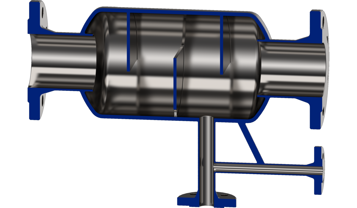
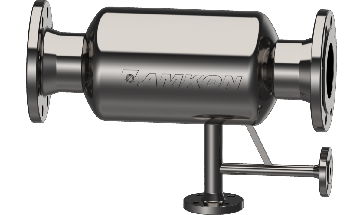
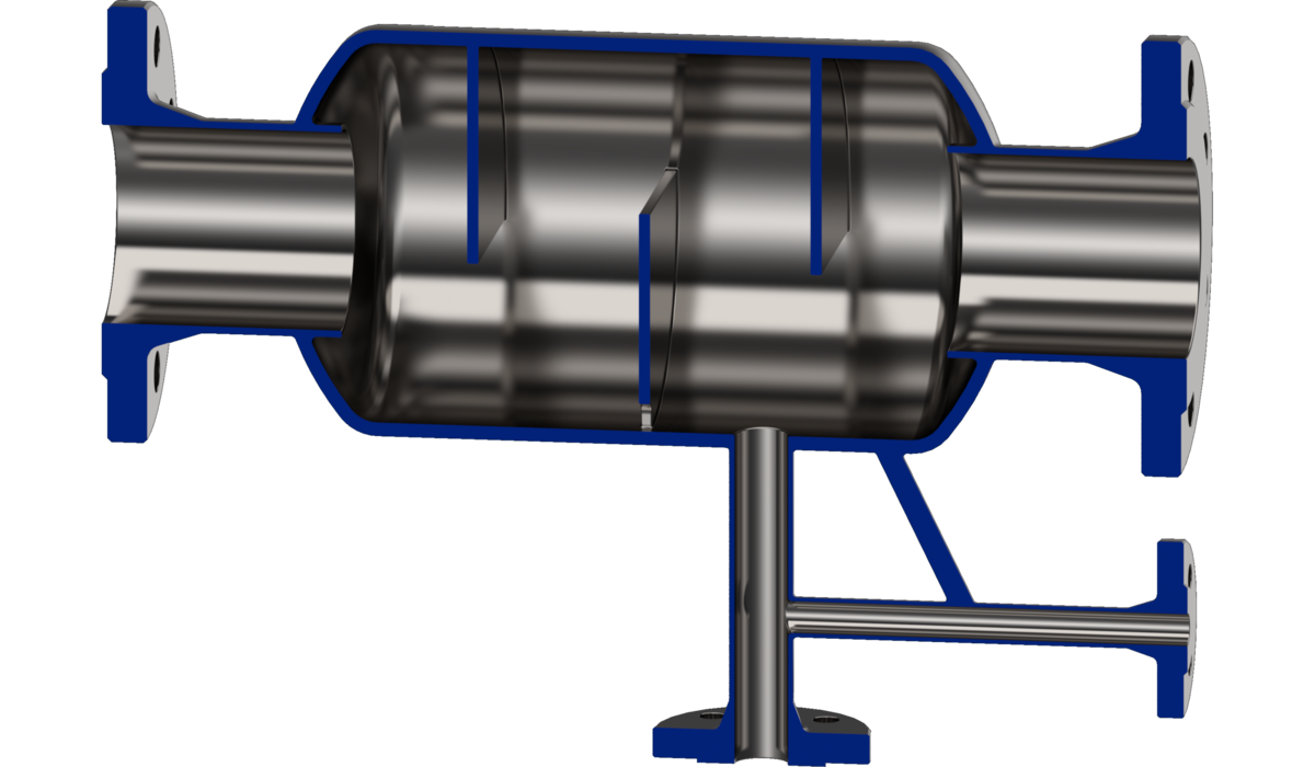
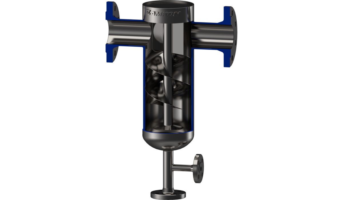
The steam separator is a pressure vessel that separates condensate from flowing steam (air). Wet steam (air) and impurities enter through connection K1; specially shaped internal baffles change the flow direction. Centrifugal force separates the denser particles, namely condensate and solid impurities, which flow down the walls to the separator bottom. Steam (air) leaves through K2, while the separated condensate and impurities flow to the bottom and are discharged through:
- K3, which must be fitted with a steam trap offering the highest resistance to impurities. It can face sideways or downwards depending on the inverted bucket trap used.
- K4 (construction option III), used to discharge impurities and normally fitted with a blind flange. It can be modified with an additional dirt collection chamber or a valve for removing accumulated sediment. For operator safety, undo the drain flange only after reducing separator pressure to atmospheric pressure.
Steam separators are installed upstream of heat consumers requiring high-quality steam (dry and free of impurities), or immediately after the main boiler outlet valve to capture temporary water carryover. Air (gas) separators are installed upstream of air consumers, such as measuring equipment or pneumatic actuators, that also require high-quality air. Insulate the separator because of its high operating temperature. Install it only in a horizontal pipeline, as shown in the drawing and in the indicated flow direction.
Downloads