
A quarter-turn indicator on a non-rising-stem gate valve
With a non-rising stem, handwheel movement does not directly provide a linear indication of wedge position. The arrangement described converts multi-turn motion into movement suitable for a quarter-turn indicator.
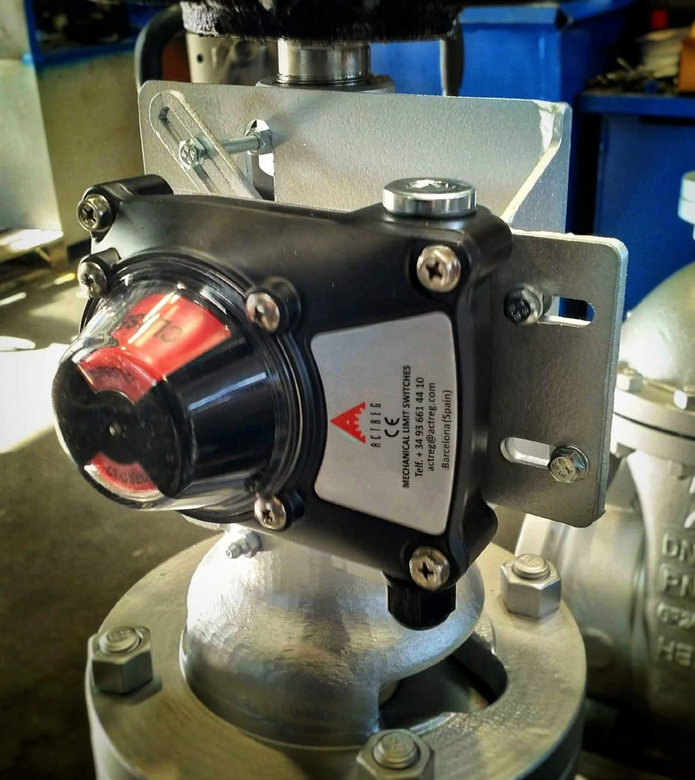
From rotation to linear travel
A nut runs on a threaded element, with rotation of the nut restricted by a guide. Stem rotation therefore produces linear travel. Travel is approximately 15–20 cm for the arrangement shown. This is not a universal stroke for all gate valves; it belongs to the illustrated assembly.
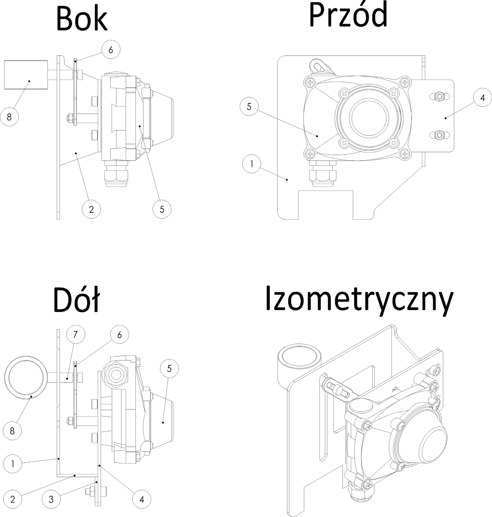
The lever moves the indicator
The moving component works with a pin and lever that transfer motion to the indicator. This connects a multi-turn mechanism with quarter-turn indication and open/closed limit switches. The drawing shows side, front, bottom and isometric views, with numbered components.
Mounting and adjustment access
Elongated mounting holes allow adjustment, while an inspection opening provides access to the assembly. A photograph of the completed assembly allows the drawing to be compared with the actual installation. Applying the arrangement requires the motion-transfer geometry to be matched to the particular valve and its end positions.