Steam tracing design: from heat losses to manifolds
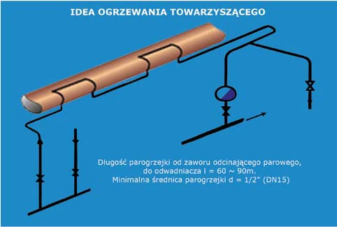
Steam tracing maintains the required temperature of a medium in a pipeline. “A design challenge” treats it as a complete system in which the tracing runs, steam supply and condensate discharge must be designed together.
Start with the heat balance
The design starts with the required product temperature and the available steam conditions. Heat losses depend on factors including insulation, heat transfer and minimum ambient temperature. Duty is established for individual loops and then for the system as a whole. Selecting a tracing tube size alone does not establish whether the product will remain at its required temperature.
A loop must be identifiable and drained
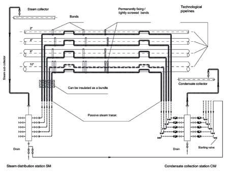
Both ends of each loop need clear identification, consistent between design documents, installation and operation. Routing, supports and thermal expansion compensation are part of the design. Trap selection depends on pressure and load behaviour, while grouping drainage points makes them easier to inspect.
RFM and ZFM as complete stations
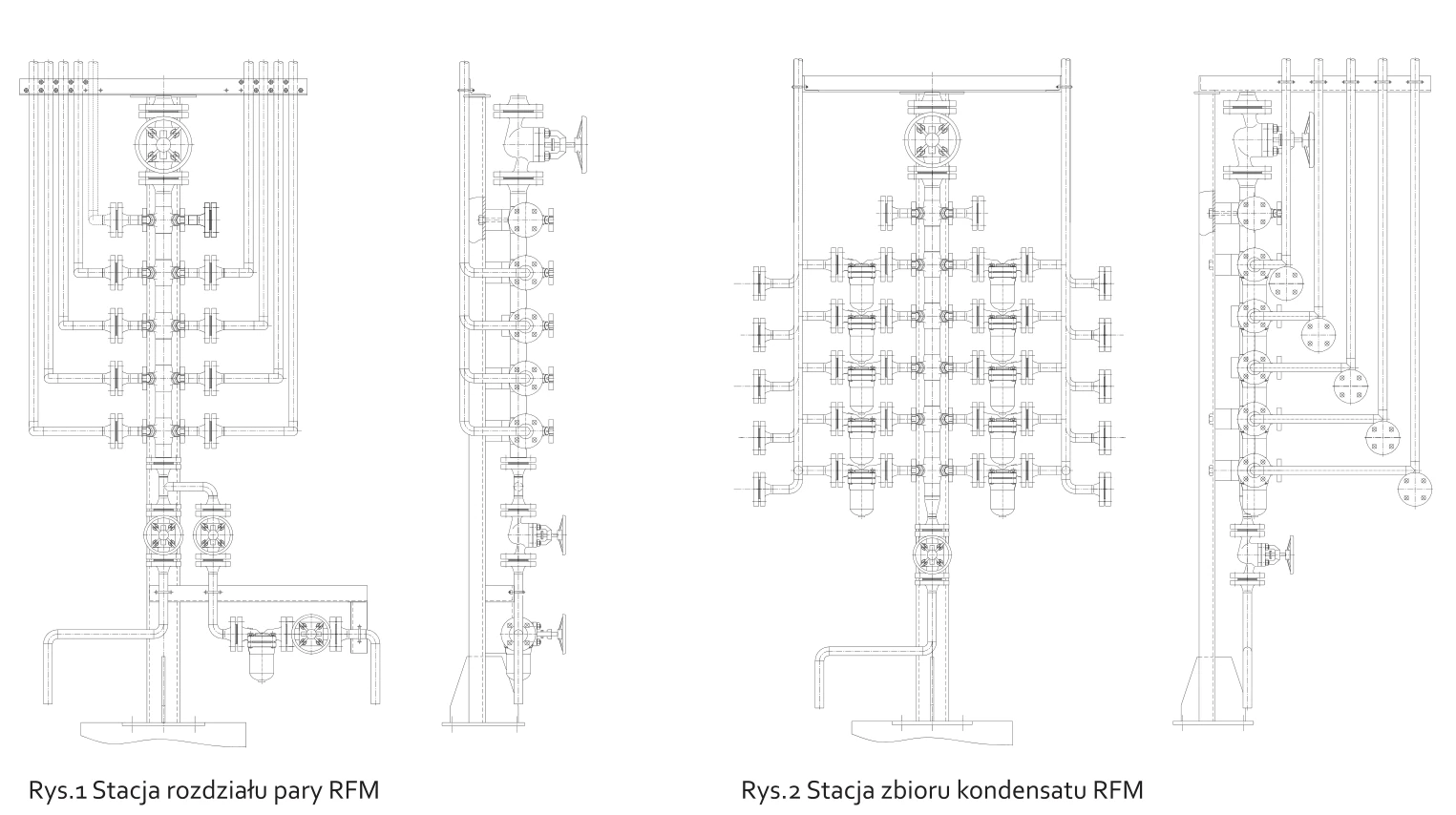
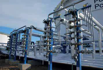
RFM stations distribute steam to the loops, while ZFM stations collect condensate. The manifolds described use a modular construction and replaceable valve components. A prefabricated, tested assembly reduces the work needed on site. This arrangement uses inverted bucket traps with check valves, with low-pressure limits for bimetallic traps: the recommended pressure is at least 3 bar, with possible instability below 2.5 bar, especially when colder condensate is continuously present on the outlet side. These recommendations apply to the arrangement described and should not be treated as a common rule for every installation.