Steam tracing: loop routing and condensate collection
Satellite heating is another name for steam tracing. Steam in a tracer transfers heat to the process pipe, and the condensate produced must leave each circuit.
The loop within the wider system
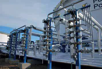
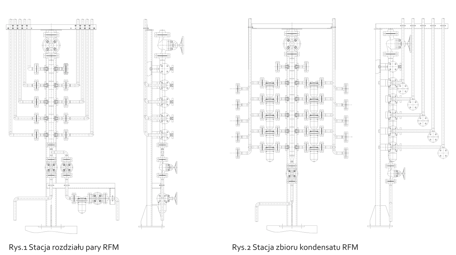
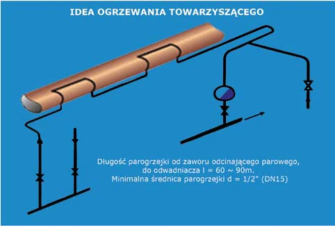
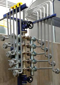
An RFM station distributes steam between loops, while ZFM stations group the traps and collect condensate. The diagram shows separate steam supply and condensate discharge paths. The tracing route needs to be considered together with insulation, the medium’s temperature requirement and the available supply conditions. Photographs show completed stations as well as the system concept.
Length and expansion compensation
DN15, DN20 and DN25 tracers require compensation for thermal expansion. For the 25 mm line described, the optimum length is 60–80 m, with a 90 m limit. These guidelines concern the arrangement presented, not a universal allowable length for every process. The final arrangement depends on the heat duty, steam conditions and ability to remove condensate.
Drainage and station access
Selection includes inverted bucket and bimetallic traps; pressure above 0.4 MPa is recommended for the latter in this arrangement. Standardising trap types is intended to simplify operation of a particular system. Grouping the points makes inspection possible without searching a dispersed installation for each trap. The completed projects remain historical examples and do not establish a project’s present status.